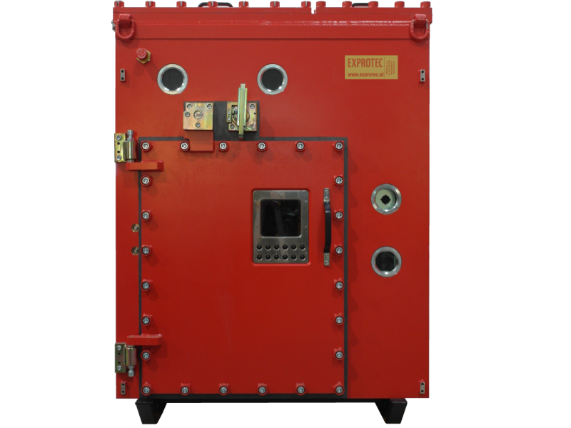
Flameproof circuit breaker type FCB
The flameproof switchgear type FCB is intended for use in workings of underground mines in non-hazardous or hazardous areas, classified as a, b or c level of methane explosion hazard and/or in workings classified as class A or B of coal dust explosion hazard.
It is designed for distribution of electricity in insulated “IT” networks 3×6 kV or 3×3, 3 kV or 3 kV.
The FCB switchgear is a fixed indoor switchgear system designed for both to be combined as multi-feeder switchgear and feeders intended for supplying individual isolated loads.
When combining feeders into multi-feeder switchgear, feeders placed side-by-side are connected with single-core flexible cables routed in metal sheaths. Customers may order the following switchgear versions:
- Incoming feeder identified by the symbol FCB-6/630/2
- Outgoing feeder (motor, cable, or transformer) identified by the symbol FCB-6/200/2.
The switchgear FCB is made up of four flameproof compartments:
- cable(s) (rubber cable) connection compartment for the power supply;
- disconnector and earth switch compartment;
- main compartment equipped with switchgear, measuring, protection and control equipment;
- connection compartment with cable(s) (rubber cables) supplying loads with power;
The main compartment equipment includes the following:
- single-phase auxiliary transformer;
- three current transformers;
- one earth fault transformer (the so-called Ferranti transformer);
- three three-coil voltage transformers;
- self-powered protection unit designed to protect against the effects of phase-to-phase fault, line-to-earth fault and overloads in medium voltage networks;
- vacuum circuit breaker;
- three single-phase surge arresters;
- separators for digital intrinsically safe and non-intrinsically safe control;
- three control switches;
- voltmeter;
- microprocessor controller with a panel to visualising the feeder status capable of recording and viewing events.
The FCB-6/*/2 switchgear is designed for control:
- local;
- remote binary signals;
- digital with visualisation from master dispatching system.
The method of controlling the switchboard is determined by the customer.

Explosion protection
Marking
I M2(M1) Ex d [ia ib] I Mb
PB Exd[ia][ib]I
Certificate
TEST 16 ATEX 005X
TC BY/112 02.01. 103,00152
Rated values
Ingress protection rating
IP55
Ambient temperature
-5°C ÷ 40°C
Maximum insulation voltage Um
7,2 kV
Rated voltage Un
6 kV or 3.3 kV or 3 kV
Rated current In
maximum 630 A depending on the current transformer
Rated short-circuit making capacity Iw
16 kA
Rated short-circuit breaking capacity Iu
40 kA
Rated short-circuit duration
1 second
Serial link type
RS485 MODBUS RTU, PROFIBUS-DP
Weight
approx. 2200 kg
Dimensions WxHxD [mm]
1315x1570x1320
Coding
| F | C | B | – | 6 | / | * | / | 2 |
| A |
| A | 200 – execution as a drainage bay 630 – execution as a supply (inflow) field |
