Intrinsically Safe and Non-Intrinsically Safe Circuits Relay Separator type PSOI
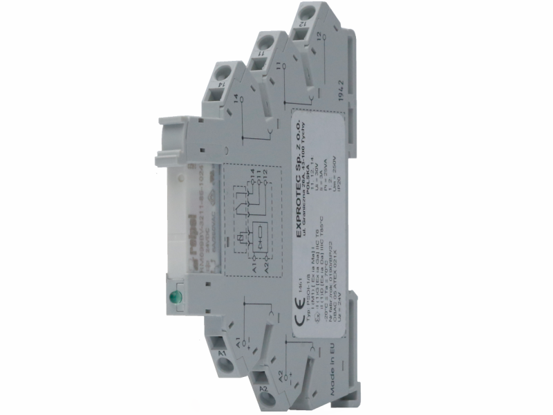
The relay separator of intrinsically safe circuits is designed to separate non-intrinsically safe and intrinsically safe circuits.
In the non-intrinsically safe circuit there is a relay coil of the PSOI separator, while its contact can be switched to intrinsically safe circuits of protection rating ia or ib.
The relay separator of intrinsically safe and non-intrinsically safe circuits PSOI thus provides information from non-intrinsically safe control circuits to intrinsically safe or non-intrinsically safe circuits of automation systems.

Explosion protection
Marking
I (M1) [Ex ia Ma] I
II (1)G [Ex ia Ga] IIC T6
II(1)D [Ex ia Da] IIIC T85°C
Ambient temperature
-40°C to + 55°C or-40°C to + 70°C
Certificate
OBAC 05 ATEX 021X
Rated values
Ingress protection rating
IP20
Intrinsically safe contacts
Contact material
Au
Load current – switching
3/0.6 A
Circuit switching voltage
intrinsically safe AC/DC
30 V
Rated AC switching power
25 VA
Max. switching power AC (250 V)
25 VA
Minimum switching current
12/5 V/mA
Relay coil
Control voltages AC (50/60 Hz)/DC
12–24-42/48-60-110…125-230..240 V
Voltage range AC (50/60 Hz)
(0.8… 1.1) Un
DC voltage range
(0.7…1.2)Un
Mechanical data
Mechanical strength
10 x 106
Electrical Strength – switching
60 x 104
Switching time
7/11 ms
Insulation strength EN 61810-5
4 kV / 3
Open contact insulation strength (AC/DC)
1000 V
Selection Chart | |
Contact type | Code |
Changeover contact | 1 |
Make contact with diode | 2 |
NO contact with NAMUR system | 3 |
NO contact | 4 |
Coil voltage | Code |
Coil voltage 12 V AC / DC | 1 |
24 V AC / DC coil voltage | 2 |
Coil voltage 42/48 V AC / DC | 3 |
Coil voltage 60 V AC / DC | 4 |
Coil voltage 110… 125 V AC / DC | 5 |
Coil voltage 220… 240 V AC / DC | 6 |
12V DC coil voltage | 7 |
24 V DC coil voltage | 8 |
24 V AC / DC coil voltage | 9 |
Coil voltage 42/48 V AC / DC | 10 |
Coil voltage 230 V AC | 11 |
Coding
P | S | O | I | – | * | * |
A | B |
A | Contact type: 1 – Changeover contact 2 – NO contact with diode 3 – NO contact with NAMUR system 4 – NO contact |
B | Coil voltage: 1 – 12 V AC / DC 2 – 24 V AC / DC 3 – 42/48 V AC / DC 4 – 60 V AC / DC 5 – 110 … 125 V AC / DC 6 – 220 … 240 V AC / DC 7 – 12 V DC 8 – 24 V DC 9 – 24 V AC / DC 10 – 42/48 V AC / DC 11 – 230 V AC / DC |